A BLTouch sensor will automate your 3D printer bed leveling. Read on to learn all you need to know about this sensor and it’s setup on your Anet A8 plus.
Mechanical
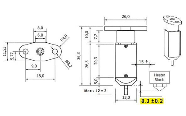
You will need a suitable mount to attach the BLTouch sensor to your printer.
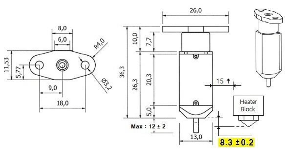
There is a lot of example on the internet. You can find the one I use here:
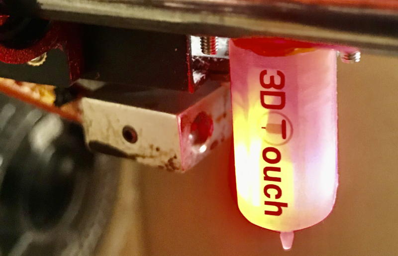
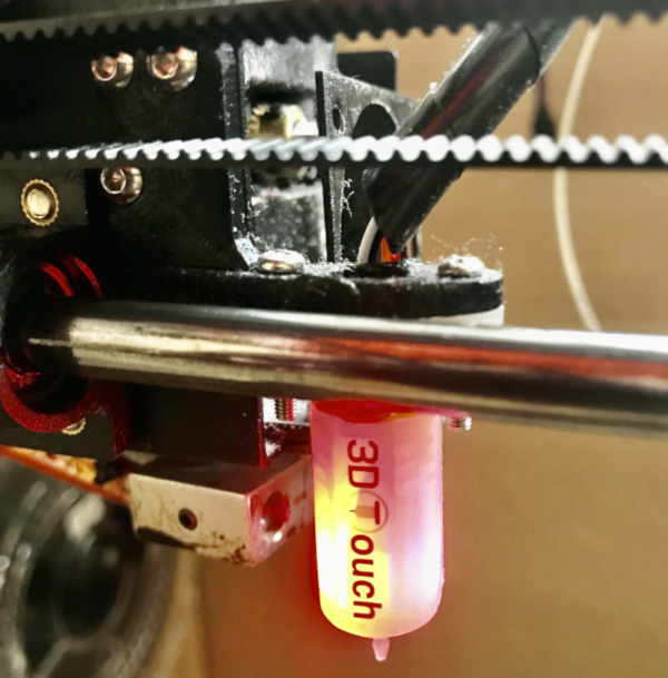
Here is a pic of our setup:
Electrical
The BLTouch sensor has 5 wires:
- 3 to the first servo connection and 5v
- 2 to the Z min end stop, negative and signal pins.
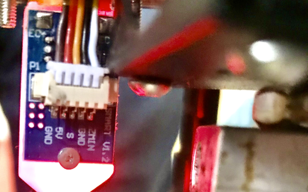
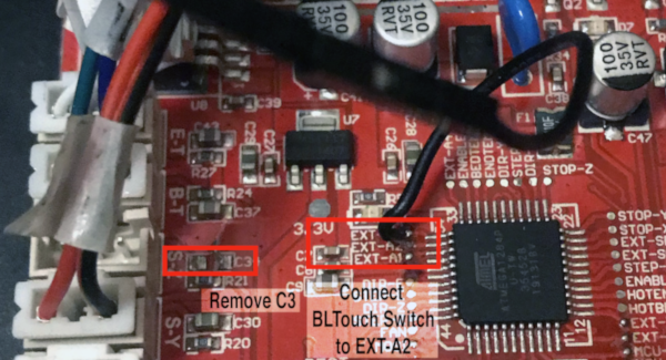
You will have to do a litle bit of solrdering rework on the anet A8/A8 plus mother board in order to connect the BLTouch leveling sensor properly. The first thing to do is to remove the deboucing capacitor C3. Then you can connect the BLTouch S signal to the EXT-A2 point of the Anet A8/A8 plus mother board (this solder point is easier to solder than the one on J3).
Connect the connector to the motherboard using the S-Z slot and the following pinout.
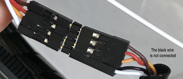
Finally you can connect the cables to the BLTouch sensor.
NOTE: The black wire is not connected since both GND signals are connected on the BLTouch circuit board
Software
Arduino IDE and board definition
You first need to install the Arduino IDE from the official Arduino website (just follow the installation instructions, as the software is easy to install on most platforms).
Then, you must get back the Anet A8 board design and add it to the boards list of the Arduino software, required for firmware compilation. he Anet board design description can be downloaded on github.
Firmware
Now that the IDE is ready, a new Firmware supporting the 3D Touch must be flashed on the Anet A8/A8 plus board. This firmware is Marlin, an Open-Source firmware for various 3D Printers. First you must download the Marlin project source code:
- Clone Marlin Firmware:
git clone https://github.com/MarlinFirmware/Marlin.git
The BLTouch needs changes made to the configuration.h file in the Marlin source code in order to handle the BLTouch sensor. The required changes are similar to how you would setup a mechanical servo sensor.
WARN: As the bootloader of the printer is not flashed in this howto, the firmware is not compressed and as a consequence, the SD card support has been removed. this should not be a problem if you use an OctoPrint server to communicate with your Printer (typically an OctoPi fitmware using a Raspberry PI)
Here is the configuration we have made for our own printers, download them and move them to the Marlin/Marlin directory (same directory than the Marlin.ino file):
- Copy Configuration.h to
Marlin/Configuration.h - Copy Configuration_adv.h to
Marlin/Configuration_adv.h
Now that Marlin is configured, open Marlin.ino with Arduino IDE, choose Anet 1.0 board and corresponding port and press Upload.
WARN Select Anet 1.0, the other is for boards with updated bootloader
Testing
When the BLTouch is first powered up it does a self test - Starting with the pin up it them goes down/up 3 times and ends up the the LED on solid.
The BLTouch acts on the following gcode that can be used manually to diagnose faults etc but you don’t need to normally worry about them.
| GCode | Description |
|---|---|
M280 P0 S10 |
pushes the pin down |
M280 P0 S90 |
pulls the pin up |
M280 P0 S120 |
Self test – keeps going until you do pin up/down or release alarm |
M280 P0 S160 |
Release alarm |
The BLTouch has two fonctional modes:
- Alarm/Continuous flashing – The BLTouch can sense when something is wrong and then goes into alarm mode. Alarm can be triggered like an obstruction that stops the pin going up and down freely, it could be dirt etc.
- Printing - Providing the firmware is correctly configured the sensor responds to the same codes as any other sensor eg inductive, capacitive or IR. The Start Code in you slicer should contain the sequence
G28followed byG29to do the auto bed levelling. (don’t put anotherG28after the G29 as it will just remove theG29results).
Calibration using GCODE instruction
This process also assumes that the EEPROM has been enabled in Marlin. From the command window of Repetier Host or Octoprint Host. enter the following:
| GCode | Description / instruction |
|---|---|
M851 |
note the number |
M851 Z0 |
set the offset to zero |
G28 |
|
G1 Z0 |
The LCD display should show Z = 0
If you have sets the software endstops in your firmware ([XYZ]_MIN_POS to [XYZ]_MAX_POS), you may have to disable the software endstops.
| GCode | Description / instruction |
|---|---|
M211 S0 |
Optionally enable/disable software endstops, then report the current state. |
ow place a 90g paper sheet under the nozzle and adjust the height of the Z axis: You have two options.
From the display menu
- go to the Menu then Prepare/Move axis/0.1mm/Move Z
- move the Z axis slowly down until the nozzle is the right distance from the build plate (folded piece of paper or thin card).
- Note the Z axis value on the display it should be something like -1.5
Using Gcode:
| GCode | Description / instruction |
|---|---|
G0 Z-0.1 |
Move down Z (Reapit until the nozzle is the right distance from the build plate (folded piece of paper or thin card). |
Now you can save the Z value and set the software endstops:
| GCode | Description / instruction |
|---|---|
M851 Z-1.5 |
to set the offset you got in the previous step. |
M211 S1 |
Enable software endstops then report the current state. |
M500 |
Stores the values in EEPROM so that it is not reset when you power the printer off and on. |
Thats it – you are ready to print.
If you find that you need to increase or decrease the gap then do:
| GCode | Description / instruction |
|---|---|
M851 Z-1.4 |
this would make the gap bigger |
M851 Z-1.6 |
this would make the gap smaller |
M500 |
to save the value to EEPROM |
NOTE: Remember the -1.4, -1.5 and -1.6 are just examples , yours will be different If your firmware isn’t setup to allow negative z movement (
#define min_software_endstopsfalse) you will need to measure/estimate the negative value to enter with the M851 command.
Calibrating BLTouch from LCD display controls.
Assumptions:
- The value of
PROBE_OFFSET_FROM_EXTRUDERis set at-2in Marlin configuration.h if it is set at something else take that into account in the formula below.
#define Z_PROBE_OFFSET_FROM_EXTRUDER -2 // Z offset: -below [the nozzle] (always negative!)
Initial setup
Let’s now setup the printer according to the new configuration:
Control > Restore failsafe(start with default settings if first installation)Prepare > Auto homePrepare > Move axis > Move 0.1mm > Move Z- Slowly move the Z axis down until you have the correct first layer gap (paper or thin card method)
- Note the distance on the display e.g. 0.6 mm (0.6 mm is example, note your actual)
- Use this formula to determine your Z offset needed: e.g. Z offset = -2 + 0.6, meaning -1.4mm
Control > Motion > Z offsetand enter the value obtained above e.g. -1.4 in this exampleControl > Store memory
Fine tuning – after initial setup
The BLTouch is very accurate and consistent after the initial setup but there are times when you might want to fine tune for example for different filament materials or bed types.
Control > Motion > Z offsetand enter the new value e.g. -1.3Control > Store memory
Notes on BLTouch flashing alarm
When the BLTouch starts up initially or starts a
G28homing sequence it extends its probe and if any obstruction is found it goes in to a flashing alarm mode. An obstruction could also be dirt on the pin restricting smooth movement, in that case just clean it. Raise the nozzle by either LCD menu or host software so the alarm won’t just happen again. Then there are 3 ways to reset the alarm:
- Power down/up again
- Frome host software send this gcode
M280 P0 S160- Some printer manufactures have added Reset BLTouch to the LCD menu
Questions ?
| Any questions, remarks ? Contact us on any of our social networks or communications interfaces ! |
|