Here are some tips and tricks to help you learn how to set up a 3D printer the first time. Start printing in no time. Get started now!
Requierements
- Software:
- Marlin FW
- Octoprint / Screen (3D printer console access).
- Hardware:
- 3D printer :-)
ZOffset with BLTouch
Calibration using GCODE instructions
This process also assumes that the EEPROM has been enabled in Marlin. From the command window of Octoprint Host. enter the following:
| GCode | Description / instruction |
|---|---|
M851 |
note the number |
M851 Z0 |
set the offset to zero |
G28 |
|
G1 Z0 |
The LCD display should show Z = 0
If you have sets the software endstops in your firmware ([XYZ]_MIN_POS to [XYZ]_MAX_POS), you may have to disable the software endstops.
| GCode | Description / instruction |
|---|---|
M211 S0 |
Optionally enable/disable software endstops, then report the current state. |
ow place a 90g paper sheet under the nozzle and adjust the height of the Z axis: You have two options.
From the display menu
- go to the Menu then Prepare/Move axis/0.1mm/Move Z
- move the Z axis slowly down until the nozzle is the right distance from the build plate (folded piece of paper or thin card).
- Note the Z axis value on the display it should be something like -1.5
Using Gcode:
| GCode | Description / instruction |
|---|---|
G0 Z-0.1 |
Move down Z (Reapit until the nozzle is the right distance from the build plate (folded piece of paper or thin card). |
Now you can save the Z value and set the software endstops:
| GCode | Description / instruction |
|---|---|
M851 Z-1.5 |
to set the offset you got in the previous step. |
M211 S1 |
Enable software endstops then report the current state. |
M500 |
Stores the values in EEPROM so that it is not reset when you power the printer off and on. |
Thats it – you are ready to print.
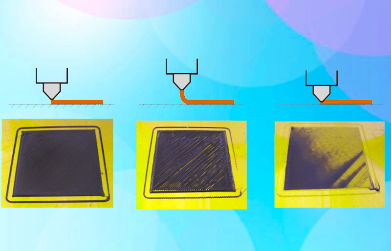
In order to test your setup we recomand to use this file flat.
If you get any trouble when printing you should have a look to and adjust your Z-offset.
If you find that you need to increase or decrease the gap then do:
| GCode | Description / instruction |
|---|---|
M851 Z-1.4 |
this would make the gap bigger |
M851 Z-1.6 |
this would make the gap smaller |
M500 |
to save the value to EEPROM |
NOTE: Remember the -1.4, -1.5 and -1.6 are just examples , yours will be different If your firmware isn’t setup to allow negative z movement (
#define min_software_endstopsfalse) you will need to measure/estimate the negative value to enter with the M851 command.
Calibrating BLTouch from LCD display controls.
Assumptions:
- The value of
PROBE_OFFSET_FROM_EXTRUDERis set at-2in Marlin configuration.h if it is set at something else take that into account in the formula below.
#define Z_PROBE_OFFSET_FROM_EXTRUDER -2 // Z offset: -below [the nozzle] (always negative!)
Initial setup
Let’s now setup the printer according to the new configuration:
Control > Restore failsafe(start with default settings if first installation)Prepare > Auto homePrepare > Move axis > Move 0.1mm > Move Z- Slowly move the Z axis down until you have the correct first layer gap (paper or thin card method)
- Note the distance on the display e.g. 0.6 mm (0.6 mm is example, note your actual)
- Use this formula to determine your Z offset needed: e.g. Z offset = -2 + 0.6, meaning -1.4mm
Control > Motion > Z offsetand enter the value obtained above e.g. -1.4 in this exampleControl > Store memory
Fine tuning – after initial setup
The BLTouch is very accurate and consistent after the initial setup but there are times when you might want to fine tune for example for different filament materials or bed types.
Control > Motion > Z offsetand enter the new value e.g. -1.3Control > Store memory
Notes on BLTouch flashing alarm
When the BLTouch starts up initially or starts a
G28homing sequence it extends its probe and if any obstruction is found it goes in to a flashing alarm mode. An obstruction could also be dirt on the pin restricting smooth movement, in that case just clean it. Raise the nozzle by either LCD menu or host software so the alarm won’t just happen again. Then there are 3 ways to reset the alarm:
- Power down/up again
- Frome host software send this gcode
M280 P0 S160- Some printer manufactures have added Reset BLTouch to the LCD menu
E-Step Calibration & Extruding
If you’ve upgraded certain parts, like switching to direct drive or a dual drive extruder, you’ll need to recalibrate the E-Step to avoid over or under-extrusion.
- Power your printer and use the menu in oder to go into
Temperatureand thenNozzlemenu. - press the
+symbol to increase the temperature to printing temps to the temperature you normally print at (190-210°C for PLA filament). - After the nozzle has heated: go back into the menu and then into
Motion–Move Axis–Extruder–Move 10mm. - Feed 100mm of filament through the nozzle 10mm at a time. Make sure the filament is extruding from the nozzle at an even rate. This is to prime the nozzle before testing.
WARN Don’t feed too much filament through at once. If you turn the dial up straight to 100mm, the gears might grind because they will try to pull too quickly.
- Take a marker and draw a line on your filament at 100mm from the nozzle entrance.

- Once you’ve slowly fed 100mm through according to the display, it’s time to take physical measurements. Measure the distance from the extruder to the mark that you made previously and make a note of it.

WARN For optimal results, do not hesitate to run through the above steps two or three times before entering a new value into the E-step.
- Once you have a few measurements, you can get the average of them to get a more accurate figure for calibration. Here’s my example:
WARN FIXME (27.02 + 28.35mm + 27.93mm) / 3 = 27.76mm average. Now let’s subtract the average length of 27.76mm from 120mm, which gives us 92.24mm. Considering we set 100mm of filament to go through on the control panel, we can now see that only 92.24% of it actually made it through. This is the definition of under-extrusion and we need to bump up the value on the E-step to correct the problem. To determine how much we need to increase the value, divide the current value of 93 with the measured average value of 92.24mm and multiply it by 100 to get a percentage.
This is the new E-step value:
(93 / 92.24) * 100 = 100.82
- In the menu, go to
Configuration–Advanced Settings–Steps/mm–E-Steps/mm - Increase or decrease the E-step value according to the result you got with your measurements.
- Go back to
ConfigurationandStore Settingsto save the values. Here’s how to get there in touchscreen mode:
We do recomand using Octoprint and the Calibration plugin to setup the E-Steps value.
Flow rate & wall thinkness
If your printer’s flow rate isn’t adjusted properly, you’ll end up with wall thicknesses that don’t match up to the preview in your slicing software. The same applies to the infill. If the flow rate is too high, the infill will be more dense than projected. If it’s too low, the infill may not be enough to support the part. The flow rate also depend of the type materials of your fillament: different filaments and materials will feed through at different rates.
Flow rate setting
The flow rate setting, is a setting that you can adjust to determine the amount of filament to be fed through. In theorry you should fine-tune the setting according to the filament type you are using. The default value is either 1 or 100%, depending on the slicer.
Bad Flow rate: symptoms
A high flow rate will lead to excessive filament use, while a low flow rate will reduce the print quality and structural integrity.
Flow rate calibration
Calibrating your flow rate (extrusion multiplier) will ensure you are getting the optimal volumetric flow from your hot end. This will all you to produce dimensionally accurate prints. After this process mating parts should also fit together correctly.
WARN Before we calibrate the flow rate, it’s important to calibrate the E-Steps because that’s a part of what determines the amount of filament being fed through the extruder.
Flow rate calibration is extremely simple and can be completed in less than 30 minutes using the process below.
- Download the test cube STL
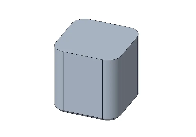
- Modify your existing slicers settings to match the list below
Line Width: 1.2X Nozzle Diameter (Ex. 0.4mm Nozzle = 0.48mm Line Width) Layer Height: 0.2mm (or set to your normal printer layer height) Vase (Spiralize) Mode: Enabled (this should also make infill set to 0%) Print Speed: Set to your normal wall printing speed
-
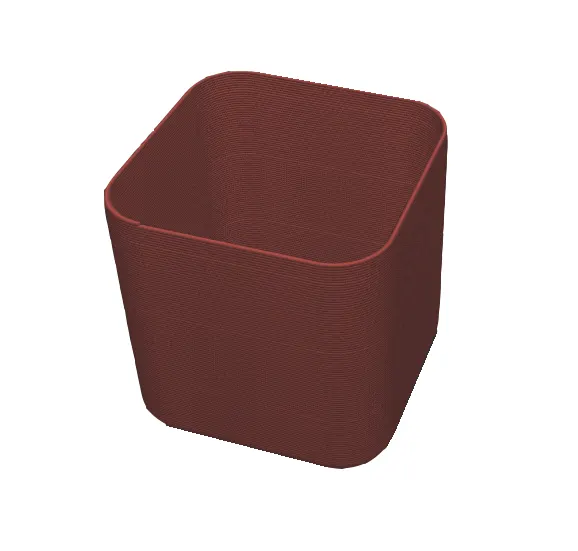
Save the gcode and begin print
-
After the print has finished and cooled, carefully remove it from the build surface and take measurements of each of the four sides. Ensure you are taking measurements towards the center of the walls.
Take the average value from measuring all walls. Now using the following formula calculate new flowrate value:
A = Expected dimension. If You are using 0.4 nozzle, expected dimension should be 0.48mm. B = Measured dimension. F = Current Flowrate.
(A / B) * F = Your new flowrate value
- Update flow rate (extrusion multiplier) in your slicer settings with the calculated value.
Temperature & PID Autotune
PID stands for Proportional, Integral, and Derivative. It controls how your printer handles temperature adjustments to your hotend and heated bed. Having these parameters calibrated will ensure you have more consistent temperatures at your hotend and heated bed which can help improve print quality.
In other words, print layers will be more consistent and your bed adhesion will be better throughout your prints due to reduced temperature fluctuations.
WARN Write down your factory PID values before making any changes in case you need to revert to the original settings.
Pimp your PID values the easy way
TLDR: Marlin comes with an PID autotune menu entry. Check your Marlin menu and select PID Autotune.
Pimp your PID values using GCODE instructions
Finding Hotend PID Values
From the command window of Octoprint Host. enter the following:
| GCode | Description / instruction |
|---|---|
MM303 E0 S240 C20 |
Run autotune for extruder 1 at 240°C for a total of 20 iterations. |
WARN It is important to pick a temperature that is close to what you typically print at. If you print at a wide range of temperatures you should pick a value somewhere in the middle of them. This will prevent you from having to rerun autotune each time you switch filament types. Also, because PID tuning is a fairly quick process I would start by running at least 10 iterations to get accurate results.
After completing the final iteration your machine will send the values it determines is the best for your machine.
Write these values down so that you can enter them into your printer in the next step. Here is a screenshot of example values of autotune results. Please note these are different from the values you will come up with.
Saving Hotend PID Values
By default, Marlin will not add the optimized value to your machine automatically. You will need to take those values and manually change your machine using the M301 command
| GCode | Description / instruction |
|---|---|
M301 P21.21 I2.31 D48.64 |
Sets hotend PID parameter to new values (yours will be different values). |
M500 |
Save these results permanently |
Finding Heated Bed PID Values
This process is almost the same as hotend tuning with the exception of using E-1. Like with the hotend, try to pick a temperature that matches what you print with or somewhere in the middle if you print at a wide range of temperatures.
| GCode | Description / instruction |
|---|---|
M303 E-1 S100 C15 |
Run autotune heated bed at 100°C for a total of 15 iterations. |
WARN Most of cheap 3D printers are unable to reach 100°C on heat bed.
Saving Heated Bed PID Values
The only difference between saving the hotend and heated bed values is that you will want to use M304 instead of M301.
| GCode | Description / instruction |
|---|---|
M304 P30.93 I2.13 D299.02 |
Sets heated bed PID parameter to new values. |
M500 |
Save these results permanently |
Questions ?
| Any questions, remarks ? Contact us on any of our social networks or communications interfaces ! |
|