Quickstarting LEIA-Solo
Congratulation ! You have received your LEIA-Solo board(s) ! Let’s start with the overall tooling and board description.
Here you will get the essentials to know in order to get your first steps with your LEIA Solo Board. Details about the hardware, software and firmware are documented here.
Software
The smartleia library expose an efficient smartcard oriented interface in order to communicate with the target. This interface is fully documented here.
Don’t hesitate to take a look to the overall LEIA-Solo documentation and tooling informations.
Hardware
Smart card interface and signal acquisition Side-channel attacks are divided into two phases: signal acquisition and signal statistical analysis. The quality of the acquisition of side-channel signal is essential to get proper results during the analysis phase. This is why the acquisition circuitry has been designed with great care.
On LEIA the leakage signal used for the side channel signals capture is the power consumption in the form of current sensing on the power lines.
Firmware
The firmware API is fully specified here and can be accessed using the python library of the smartleia library.
This library is packaged for Debian and can be installed using pip.
Tutorials
- Tutorials Repositories
- Introduction
- Flashing/Upgrading the Firmware
- Hardware Validation with the Funcard
- Automation
- LEIA Scripting
- LEIA with the Chipwhisperer
- Analysing Traces (SCA)
Measurements
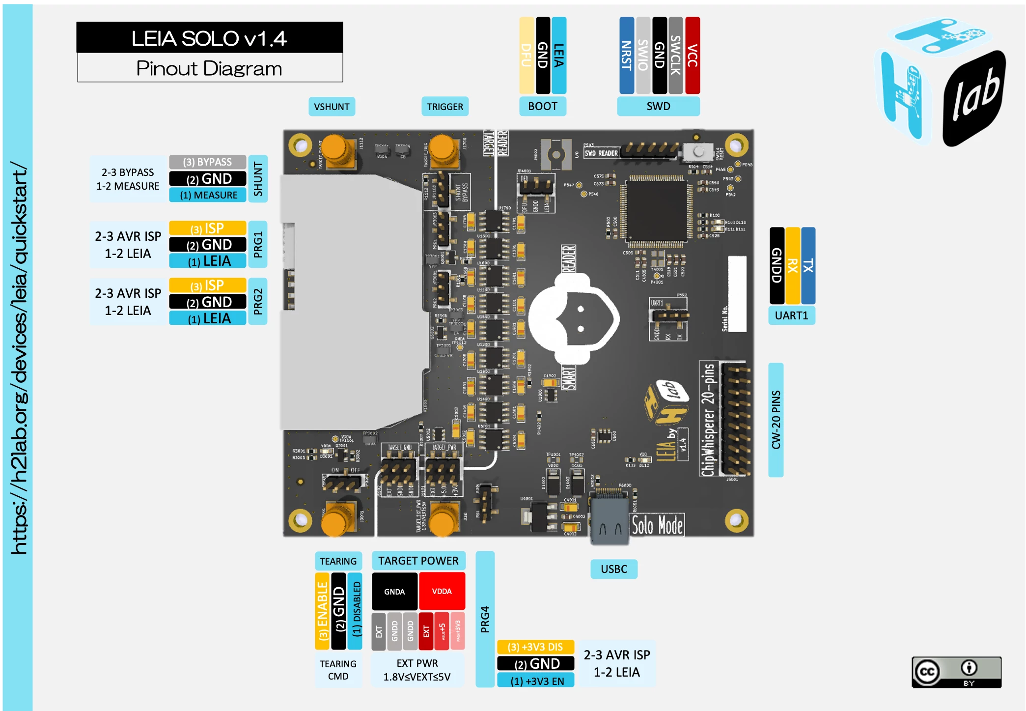
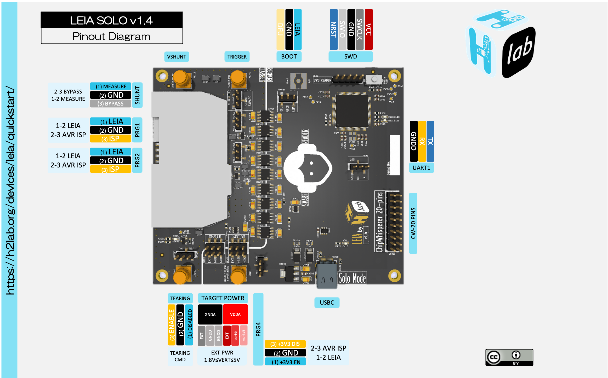
Board pinout
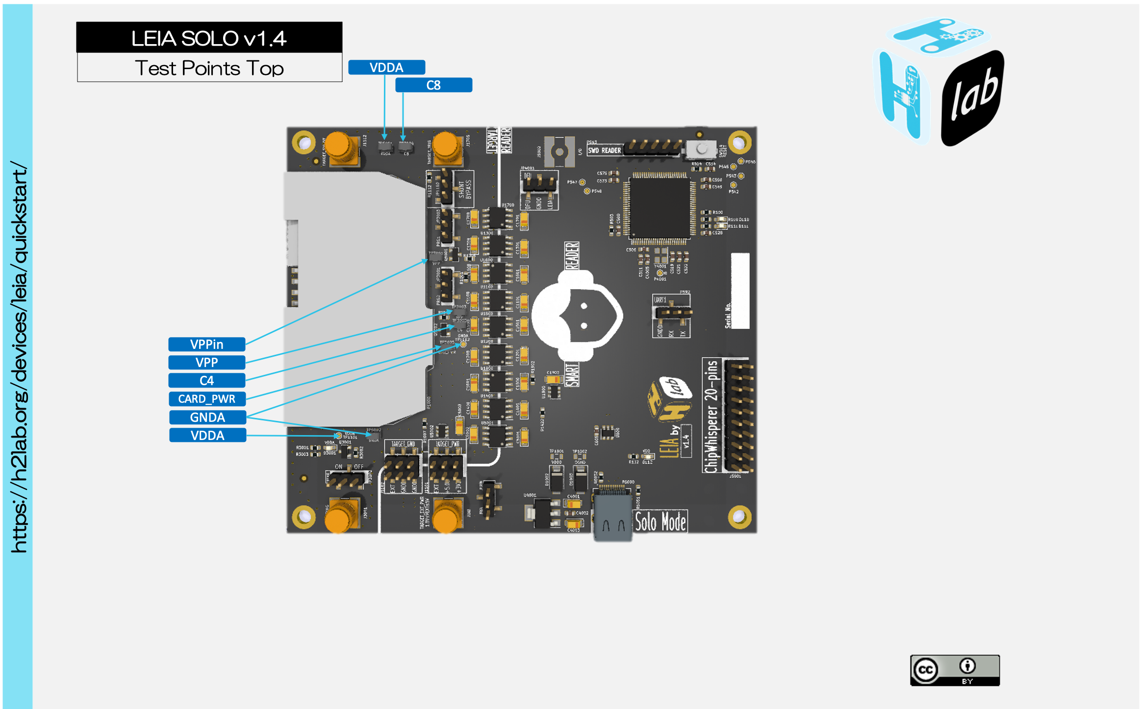
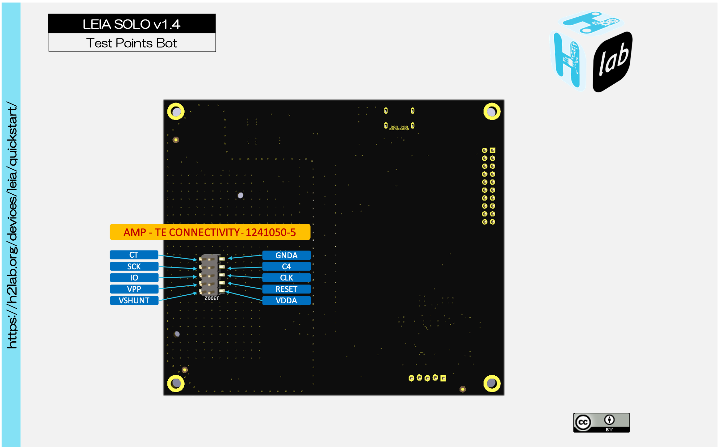
Testing points
Current sense
When sensing current, the designer can choose to place the sensors (usually a serial resistor on the power line) either between the supply voltage (VCC) and load, or between the load and ground. The former is called high-side sensing whereas the latter is called low-side sensing.
- High-side sensing has the advantage that the load is directly connected to the ground GND. In other words, there is no change on the load side except a small power drop due to the current sensor on the VCC line. Nevertheless the main disadvantage is that we have to use a differential probe to measure the current.
- In low-side sensing the current is sensed in the ground return path (GND) of the power line to the monitored load. This has the advantage to produce a ground referenced measured signal but the load is no more directly connected to GND.
In our design the target, the LEIA boards and the controling device like the Chipwhisperer can have separate power domains, since we do not want the noise produced by the power switching supply the controling device to be visible in the measurements. We choose to use a low-side measurement as it minimizes the amount of hardware to support all the power domains.
Shunt Resistor
The shunt resistor is the element that is used in a circuit to redirect currents around the measuring device. The addition of a shunt resistor induces a voltage drop at the maximum current rating. This is why the value of the Shunt Resistor must be selected carefully. Important parameters include the resistance tolerance, the power rating and the temperature coefficient:
- The power rating indicates the amount of electrical power that the resistor can dissipate at a given ambient temperature without being damaged nor changing the resistor parameters.
- The temperature coefficient describes the relative change of resistor value according to the temperature.
- Resistance tolerance is the accuracy the constructor guarantees on the component’s characteristics.
ISO7816 Class A devices, which are the most power-consuming devices among smart cards, can draw at most 160 mA for 400 ns and continuously draw at most 60 mA. We want the voltage drop at maximum current to be at most 50 mV for not disturbing nominal working of the TOE whatever class tho TOE belongs to.
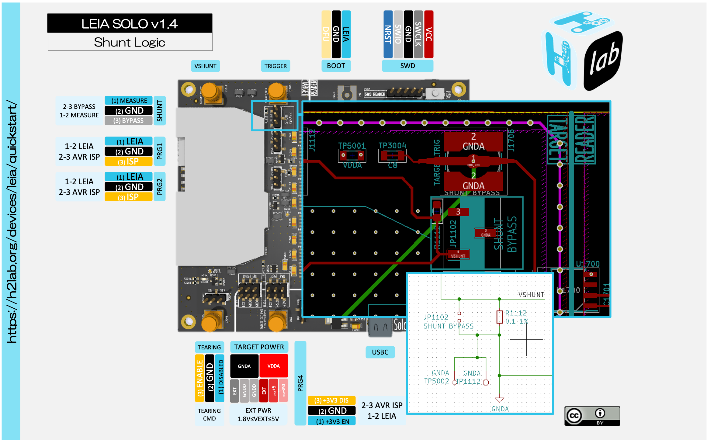
LEIA v1.4
LEIA v1.4 uses a 0.1 Ω resistor with a tolerance of 1%, a temperature coefficient of 300 PPM/C and a power rating of 100 mW. It is a widespread, easily available component that meets the needs. This resistor, as it induces a maximum voltage drop far from the limit, allows us to get clean measurements. Connectors and measurement.
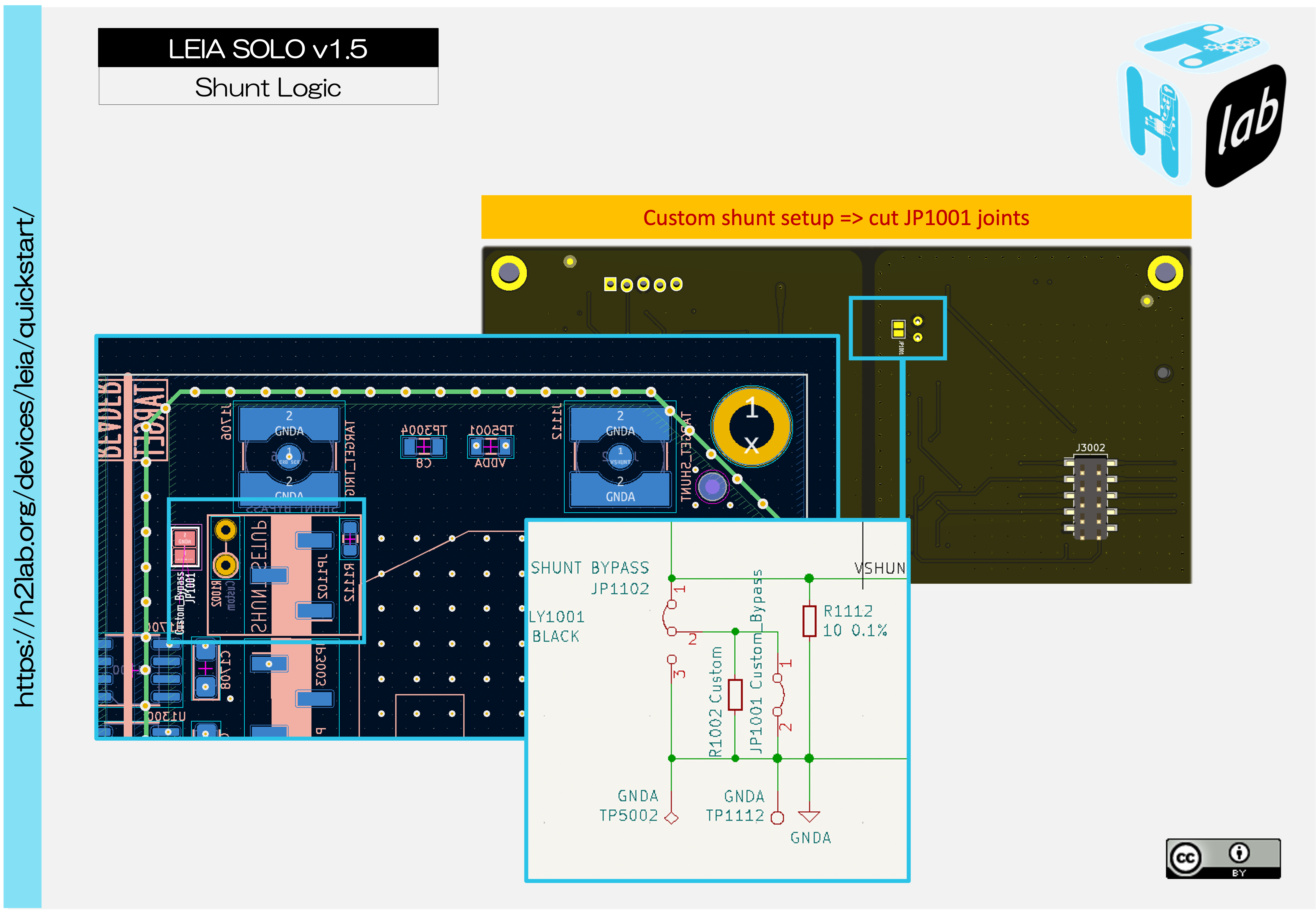
LEIA v1.5
In the default configuration LEIA v1.5 uses a 10 Ω resistor with a tolerance of 1%, a temperature coefficient of 300 PPM/C and a power rating of 100 mW.
It is also possible to install a custom resitor R1102 on the board to feet your needs. In order to Enable the custom resistor you must cut the JP1001 joints (under the board).
Measurements bandwidth
In order to provide high quality measurements, we use SMA End Launch Connectors since they offer reliable broadband performance from DC to 18 GHz with low reflection and constant 50 Ω impedance.
Because we want you to be able to measure the leaking signal from the target without any bandwidth loss we have chosen to not embed a low noise-amplifier. This allow you to caracterise the leaking signal of your target and decide which amplifier to use to get the best result.
Setting up measure Mode
In order to setup LEIA in the measure mode:
- Move the PRG1, PRG2, PRG3 (LEIA Solo < v1.4) and PRG4 to the LEIA position (1-2).
- Remove the shunt bypass jumber if it is set.
- Move the tearing jumper to the OFF position.
- Setup the power source for the smartcard. We would advise an external “clean” power source for clean measurements. However, we are able to get proper traces with the USB-C power supply on the funcard.
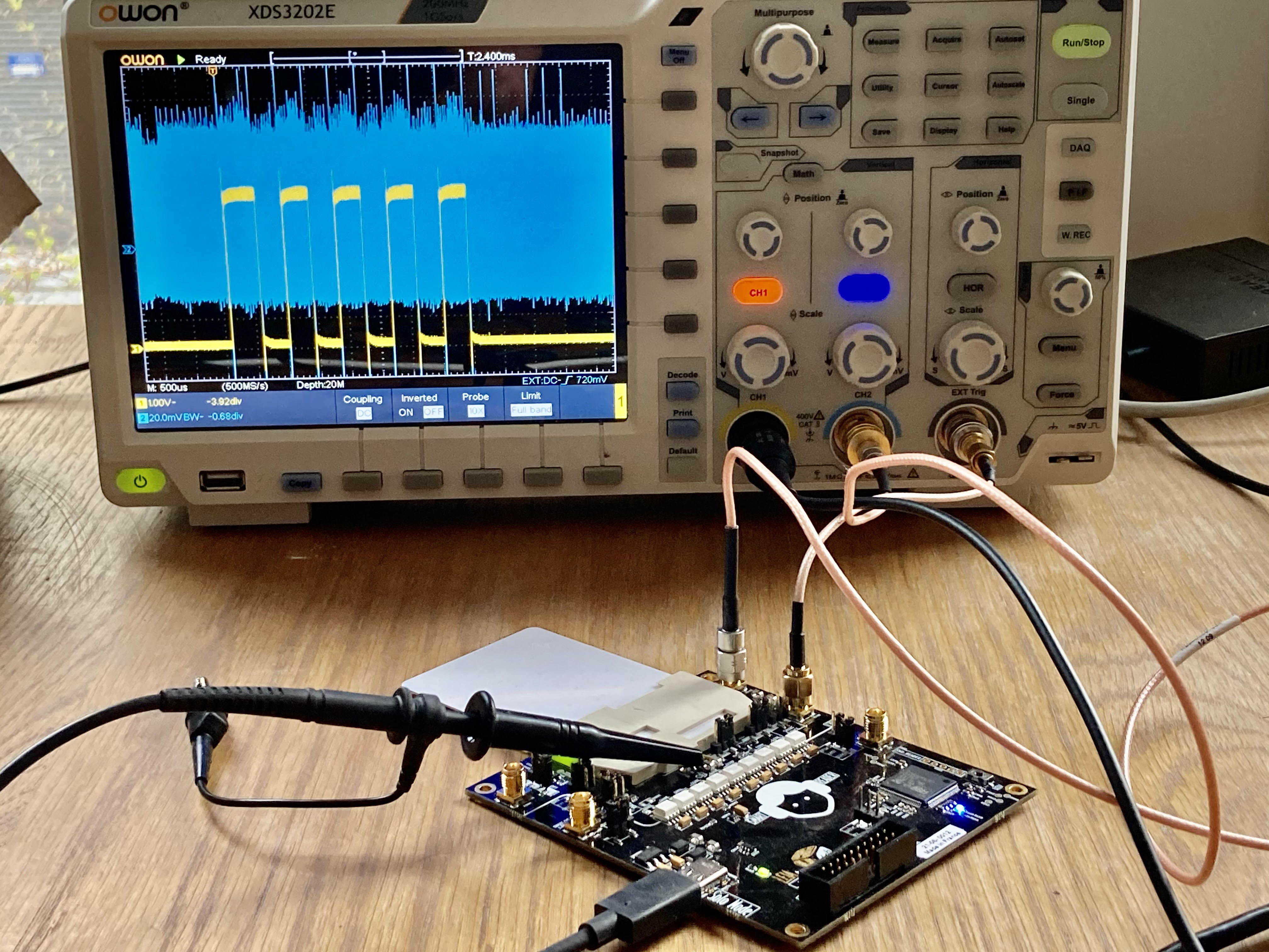
Testing setup :
- Trigger is set on EXT and connected to C8 which is configured in trigger mode 2 (Rising Slope 1V).
- C4 configured in trigger mode 1 is set on CH1. The signal is toggling at every AES round (1V/DIV).
- The Shunt signal is connected on CH2 (20mV/DIV).
- The sampling rate is set to 500MS/s with a 500us/div scale.
Setting up Funcard programming mode
In order to setup LEIA in the Funcard programming mode:
- Move the PRG1, PRG2, PRG3 (LEIA Solo < v1.4) and PRG4 to the ISP position (2-3).
- Setup the shunt bypass jumber if not set.
- Move the tearing jumper to the OFF position.
- Setup the power source for the smartcard to enable the USB-C power supply on the funcard.
Regulatory compliance & handling
The LEA board is intended for use as a development measure platform. The board is an open system design, which does not include a shielded enclosure. This may cause interference to other electrical or electronic devices in close proximity. In a domestic environment, this product may cause radio interference in which case the user may be required to take adequate measures. In addition, this board should not be used near any medical equipment or RF devices.
The board is sensitive to ESD. Hold the board only by its edges. After removing the board from its box, place it on a grounded, static-free surface.
The board can become hot, like any fan-less design, during continuous high CPU loads, mind its temperature while handling it.
Contacting H2Lab for LEIA-Solo
- Technical question: leia-faq.technical [at] h2lab.org
- Other question: leia-faq.general [at] h2lab.org
FAQ, Problems, incompatibilities
During our tests, we have found some various problems that you may encounter:
I can’t communicate with LEIA-Solo board!
1. Do not use ModemManager on GNU/Linux
ModemManager may be installed by your distribution. This service tries to communicate with any ttyACM-based device, making interactions with LEIA-Solo unstable to other tools. You may uninstall or deactivate it temporarily.
2. Check the ttyACM numbers in your dmesg
There are some cases where the udev mechanisms upgrade the ttyACM numbering dynamically for already plugged devices. You might have another ttyACM device connected. This may impact the python layer, even if we try to handle this use case and check successive devices.
3. Are you using direct access or VPCD-based access ?
If the communication is made using VPCD, the vsmartcard VPCD relay must be installed and the smartleia main loop must be executed first and keeped started in background:
$ python3 -m smartleia


        The connection with LEIA is opened and is connected to pcscd through virtualsmartcard.

        You can change the link with the smartcard with the following commands :

            configure( protocol_to_use=0,
                       ETU_to_use=...,
                       freq_to_use=...,
                       negotiate_pts=True,
                       negotiate_baudate=True)

            t0()    Equivalent to configure(protocol_to_use=0)
            t1()    Equivalent to configure(protocol_to_use=1)
            dfu()

        You have access to leia through the `leia` variable.

        Type exit() or CTRL-D to exit.


>>> Starting LEIA PCSC relay for host 127.0.0.1:35963
I didn’t manage to use LEIA-Solo as a smartcard reader
Be sure that you have installed the vsmartcard VPCD backend to your PC/SC installation. The relay is packaged under Debian Bullseye and higher:
$ sudo apt install vsmartcard-vpcd
On other distros, it can be compiled from sources. The upstream project can be found here: https://github.com/frankmorgner/vsmartcard
To check that the VPCD library is load by PC/SC, you can stop the pcscd service and run it in foreground using:
# pcscd -fad
You should get, in the pcscd logs, the following.
...
valuatetoken() Add reader: Virtual PCD
...
Questions ?
| Any questions, remarks ? Contact us on any of our social networks or communications interfaces ! |
|